THE MORTISE AND TENON JOINT
Reprint from: Woodwork Joints by William Fairham
Amortise and tenon joint is the method of joining timber by working a solid rectangular projection in the one piece and cutting a corresponding cavity to receive it in the adjoining piece. The projection is called the tenon, and the cavity the mortise. Joints of this type are secured in various ways. Small wedges, wooden dowels, metal dowel pins, glue and paint are frequently used, and prior to the introduction of glue we have examples of Egyptian furniture in which the mortise and tenon joints were united by a composition of cheese.

Fig. 127.—Barefaced Tenon Joint.
| 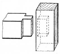
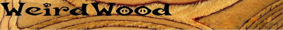
Fig. 128.—Stub Tenon.
|
Barefaced Tenons.—
Fig. 127 illustrates the joint in its simplest form and shows a tenon having only one shoulder. This is called a barefaced tenon, and it will be noticed that the portion which carries the mortise is thicker than the rail on which the tenon is cut. The joint is therefore level (or flush as it is called) on one side only, and it should never be used at the corner of a frame. It is a useful interior joint for framing that has to be covered on the back side with matchboarding, and allows the work to finish level at the back when the boarding has been applied (see plan,
Fig. 127).
Stub or Stump Tenon (
Fig. 128; also occasionally called a joggle tenon).—The illustration shows a tenon as used in the interior of a frame. The tenon is not allowed to run through the stile, and unslightliness on the edge is thus avoided. This type of tenon is often used at the corner of a frame, and it then requires to be haunched. A good workshop method of gauging the depth of the mortise for a stub tenon is shown in
Fig. 129; a piece of gummed stamp paper is stuck on the side of the mortise chisel, indicating the desired depth of the mortise. This greatly facilitates the work, as it is not necessary to be constantly measuring.
A Haunched Tenon as used at the end of a door frame is shown at
Fig. 130.—In this case it will be seen that the width of the tenon is reduced, so that sufficient timber will be left at the end of the stile to resist the pressure of the tenon when the joint is driven together. The short portion (A) which is left on the tenon is called the haunch, and the cavity it engages is termed the haunching. The haunch and haunching prevent the two pieces of timber lipping, or becoming uneven on the face side, as would be the result if it were cut away entirely up to the shoulder.
Fig. 131 shows the type of tenon and haunch used when the stile or upright rail is grooved to receive a panel. In this and similar cases the haunch is made the same width and the same depth as the groove; the groove therefore acts as the haunching. An application of this joint is shown in the top rail of the door frame,
Fig. 132.
This type of joint is also used to connect the rail to the leg of an ordinary kitchen table (see
Fig. 167).
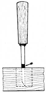 Fig. 129.—Method of Gauging for depth of Tenon.
Fig. 130.—Haunched Tenon used at end of Door Frame.
| 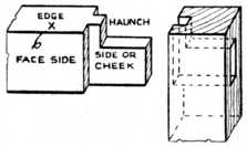
Fig. 131.—Haunched Tenon used when Stile is Grooved for Panel.
|
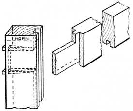
Fig. 132.—Application of Haunched Tenon Joint to Door Frame.
| 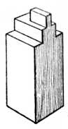
Fig. 133.—Occasional Stump Tenon.
|
Fig. 133 is a variation of the stump tenon, occasionally used where the work in hand demands a thin tenon and a stout stump to take heavy strains.
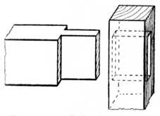
Fig. 134.—Joint for Inside Framing.
| 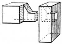
Fig. 135.—Haunched Barefaced Tenon.
|
A joint used for inside framing is seen at
Fig. 134. The rails may be used as shown, but in the case of a door frame (as
Fig. 132) they would have the inside edges grooved to receive the panels; the tenons would therefore be slightly narrower than shown, owing to the groove at each edge.
A Haunched Barefaced Tenon, used in similar positions to
Fig. 131, is shown at
Fig. 135. The door or frame in this case would be made of matchboarding nailed on the back as shown in the plan at
Fig. 127.
Wedges.—
Fig. 136 shows the method of cutting wedges which are to be used to wedge the tenons; this avoids waste of material. Some workers cut the wedges from the pieces left out of the haunching of the lock rail, or the bottom rail.
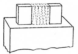
Fig. 136.—Cutting Wedges from Waste of Haunching.
| 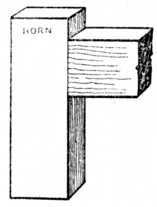
Fig. 137.—Stile and Cross Rail with Horn.
|
A Stile and Cross Rail, framed together, are shown at
Fig. 137. The portion above the rail is called the horn, and it is usual to leave sufficient length of stile to project above and below the cross rails, so that there will be no tendency for the stile to burst out at the end whilst the cramping and wedging of the frame is in progress. On completing the framing the horn is cut away.
In
Fig. 138 we have a type of joint frequently used for garden gates. The illustration shows the method of tenoning the three pieces to the top rail, barefaced tenons being employed.
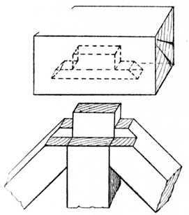
Fig. 138.—Joint used for Garden Gates.
| 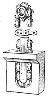
Fig. 139.— Sprocket Wheel.
| 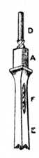
Fig. 140.— Boring Tool.
|
Sprocket Wheel.—At
Fig. 139 are shown the guide bar and chain of a chain-mortising machine, two enlarged links of the chain being indicated at A. The chain is similar in construction to the driving chain of a bicycle, with the exception that it is provided with teeth which cut away the timber as the chain revolves. When using a chain mortiser the portion of the machine carrying the chain is fed downwards into the timber, thus cutting a clean and true mortise. If, however, a stump mortise is required it is necessary to pare away a certain amount of timber by hand, because the machine obviously leaves a semicircular bottom to the mortise. To overcome this difficulty the latest types of mortising machines have a square hole-boring attachment fixed alongside the chain. This tool, the working portion of which is illustrated in
Fig. 140, consists of a square hollow chisel (E), which is sharpened from the inside, and a revolving twist bit (D) fitted with spurs or nickers, but without a point (one spur can be seen at the bottom of the illustration). This bit revolves inside the shell like a chisel, and bores away the superfluous timber, whilst the pressure exerted on the chisel causes the corners to be cut away dead square. A mortise
3⁄
8in. square by 6 ins. in depth may thus be cut. The portion marked A is the shank of the chisel (
Fig. 140), where it is fixed into the body of the machine, and the hole at E allows the boring bit to free itself.
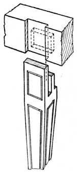 Fig. 141.—Method of Fitting an Interior Table Leg.
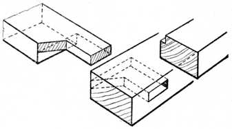
Fig. 142.—Haunched Tenon for Skylight or Garden Frame.
| 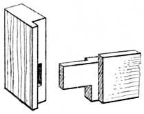
Fig 143.—Long and Short Shouldered Tenon.
|
Fig. 141 indicates the method of fixing an interior leg to a table having a circular or straight top rail. The inlaid leg in this case is stump-tenoned into the top rail, and the inlaid portion of the leg is allowed to run through the rail, thus giving continuity of design.
Fig. 142 shows the application of the haunched tenon (
Fig. 135) to the making of a skylight or garden frame. In this and similar cases the side rails are rebated as shown in the section, and the bottom rail is thinner than the side rails to allow the glass to finish level upon it.
Long and Short Shouldered Joint.—
Fig. 143 shows a haunched mortise and tenon joint having a long and short shoulder. This is a fairly common joint in framed partitions for offices, framing for greenhouses, tool sheds, etc., and is a frequent source of annoyance to the amateur. It is necessary to use this joint when both the stiles and uprights are rebated, and it calls for accurate marking out and great care in the making.
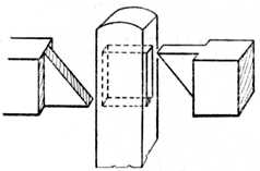
Fig. 144.—Joint for Fencing.
| 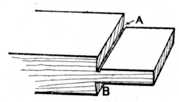
Fig. 145.—Example of Faulty Tenon.
|
Fig. 144 shows the upright and rails of common garden or field fencing. The tenons are bevelled to fit and wedge each other in the mortise. The illustration gives both cross rails as shouldered, but in many cases shoulders are omitted when the rails are not thick enough to carry them.
Fig. 145 indicates faulty methods of working a tenon. At A the saw has been allowed to run too far when cutting the shoulder, thus greatly weakening the tenon. At B faulty sawing has again occurred, and to remedy this defect the worker has resorted to paring the shoulder with a chisel. Had the chisel been used vertically an undercut shoulder (as at B) would not have occurred. The trouble now is that the slightest amount of shrinkage in the width of the stile will show an open joint. The result will be the same if it is necessary to remove a shaving or two when planing or levelling up the face of the frame.
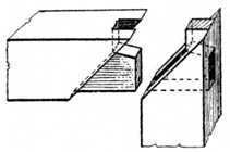
Fig. 146.—Self-wedging Japanese Tenon Joint.
| 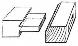
Fig. 147.—Tenoned and Scribed Joint.
|
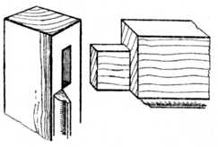
Fig. 148.—Mitred and Moulded Tenon Joint.
| 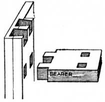
Fig. 149.—Twin Tenons.
|
A Japanese Tenoned Joint, little known and rarely used in this country, is shown at
Fig. 146. For clearness the two parts are here shown separate. The joint is self-wedging and will be of interest to Handicraft Instructors.
A Tenoned and Scribed Joint is seen at
Fig. 147. The cross rail is cut at the shoulder, so as to fit the moulding which is worked on the stile. This is a good joint in everyday use.
Mitred and Moulded Joint.—
Fig. 148 shows a type of joint largely used in light cabinet work. The method of mitreing the moulding and tenoning the stile to rail is indicated.
Twin Tenons (
Fig. 149).—The method of tenoning the bearers which carry the drawers, or the midfeather between two drawers, in a dressing table or similar carcase is here shown. On completion, the tenons on the midfeather are wedged diagonally.
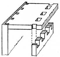
Fig 150.—Method of Pinning.
| 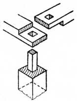
Fig. 151.—Joining Top Rails to Upright Post.
|
Pinning.—
Fig. 150 shows the tenoning of the inside end of a wardrobe to the top of the carcase. This is also called pinning. The tenons should be wedged diagonally. The tenons and the distance between the tenons are more satisfactory if made equidistant, because if slight shrinkage occurs this is partially equalised. The width between the tenons should in no case exceed 3 ins.
Top Rails.—At
Fig. 151 is shown the method of joining the top rails to the post of a tool shed or similar outhouse. The two rails, which are at right angles to each other, are half-lapped and mortised; the tenon on the post runs entirely through them.
A Tusk Tenon Joint, with wedge, as used to secure the binder to the girder when making floors, is indicated at
Fig. 153. The tenon here is narrow and engages the mortise, which is situated in the compressional fibres immediately adjoining the neutral layer.
Fig. 152 shows a tusk tenon furnished with a drawbore pin.
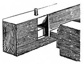 Fig. 152.—Tusk Tenon.
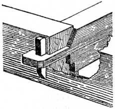 Fig. 153.—Wedged Tusk Tenon.
Fig. 155 shows tusk and wedged tenons as used when making a portable book or medicine cabinet. The shelf is housed into the end, and the tenons run through the end and are secured by wedges. This allows the article to be quickly and easily taken to pieces for removal or re-polishing. The dotted line in
Fig. 155 indicates that the shelf may be shaped if desired.
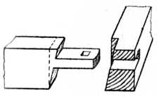
Fig. 154.—Another Type of Tusk Tenon.
| 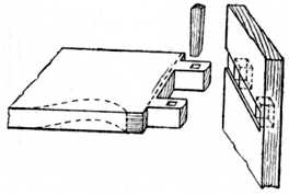
Fig. 155.—Tusk Tenon and Wedge.
|
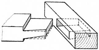 Fig. 156.—Wheelwright's Self-wedging Tenon Joint.
In
Fig. 156 a self-wedging mortise and tenon joint used by wheelwrights is shown. The dotted line (left-hand diagram) will indicate the amount of taper given to the mortise.
Dovetailed and Wedged Tenon (
Fig. 157).—When two pieces such as the cross rail and leg of a carpenter's bench are required to be held together by a mortise and tenon, and to be readily taken apart, the tenon is dovetailed on one side and the mortise is made of sufficient width to permit the widest part of the dovetailed tenon to pass into it. When the tenon is in its position a hardwood wedge is driven in above the tenon, as shown.
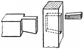 Fig. 157.—Dovetailed and Wedged Tenon.
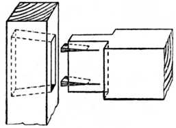 Fig. 158.—Method of Fox-wedging.
Fox Wedged Tenon (
Fig. 158).—This is the method of securing a stub tenon by small wedges. The mortise is slightly dovetailed and two saw cuts are made in the tenon about
3⁄
16in. from each side. Into each saw kerf a wedge is inserted and the joint glued up. The cramping operation forces the wedges into the saw cuts, thus causing the end of the tenon to spread and tightly grip the mortise.
Mortise and Tenon with Mitred Face (
Fig. 159).—This is a useful method of jointing framing which has square edges as shown; and it is equally useful even if the face edges have moulds worked upon them. If the joint has square edges a rebate may be formed to accommodate a panel by fixing a bolection moulding around the frame. A section of the bolection mould planted on the frame is shown in the lower figure.
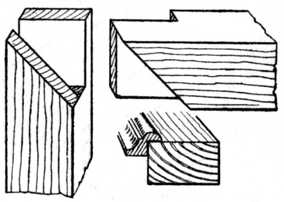 Fig. 159.—Tenon Joint with Mitred Face.
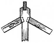
Fig. 160.—Rafter Joint.
| 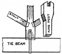
Fig. 161.—Roof Joints.
|
Roof Joints.—
Fig. 160 shows the method of tenoning the principal rafter to the king post, whilst
Fig. 161 illustrates the tenoning of the struts to the king post, and the king post to the tie beam. Both these examples are used in roof work. (See also
Fig. 71.)
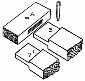 Fig. 162.—Drawbore Pinning.
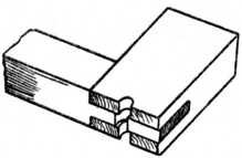
Fig. 163.
| 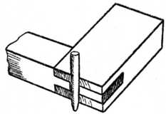
Fig. 164.
|
Operation of Pegs in Drawbore Pinning.
Drawbore Pinning.—At
Fig. 162 is seen the method of securing a tenon by drawbore pinning, employed when it is not convenient to obtain the necessary pressure by using a cramp. The joint is made in the usual manner, and a
3⁄
8-in. twist bit is used to bore a hole through piece A. The tenon is driven home and the hole is marked on the side of the tenon (B); the tenon is then withdrawn and the hole bored about
1⁄
8 in. nearer to the shoulder than as marked on the separate diagram at C. When the tenon is finally inserted the holes will not register correctly, and if a hardwood pin be driven into the joint it will draw the shoulders of the tenon to a close joint and effectually secure the parts.
Sash Bars.—
Fig. 165 shows how to tenon a moulded sash bar to the rebated cross rail. In this illustration both shoulders of the moulded bar are shown square, but in the best class work these shoulders may be slightly housed into the cross rail to prevent side play. This type of joint is used for horticultural buildings, etc. If the lower rail be moulded with the same members as the sash bar, the end of the sash bar will have to be scribed on to it to make a fit.
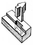
Fig. 165.—Tenoning Moulded Sash Bar.
| 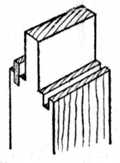
Fig. 166.—Tenon with Tongued and Grooved Shoulder.
| 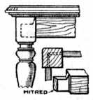
Fig. 167.—Detail of Table Framing.
|
Tenon with Tongued and Grooved Shoulders (
Fig. 166).—The object of the tongues and grooves here is to prevent the face of the work casting, or becoming warped, and thus spoiling the appearance of the surface of the work. If framing is to be veneered on the face side this is an exceptionally good method.
Table Framing.—
Fig. 167 indicates the framing of a rail to a dining-table leg. In cases similar to this the tenons run into the leg and almost touch each other. They are therefore mitred on the end as shown in the inset. Chair frames often call for similar treatment.
Twin Tenons with haunch, as used when the timber is of great thickness, are shown in
Fig. 168.
An Open Slot Mortise at the end of a right-angled frame is seen in
Fig. 169.
Fig. 170 shows an open slot mortise and tenon joint at the end of a frame of 60°. Both these joints are occasionally called end bridle joints.
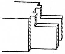
Fig. 168.—Twin Tenons for Thick Timber.
| 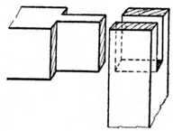
Fig. 169.—The Open-slot Mortise Joint.
|
Hammer Head Tenons.—At
Fig. 171 is shown the method of jointing framing having semicircular or segmental heads. The left-hand diagram indicates the method of wedging the joint so as to draw up the shoulders; the right-hand view shows the tongueing of the shoulders, which is necessary if thick timber has to be wrought. The sketch depicts the stile when taken apart from the shaped head of the frame.
Clamping.—
Fig. 172 shows the method of tenoning drawing boards, desk tops and secretaire falls. This is commonly called clamping. The method is used to prevent wide surfaces from winding. A variation of the joint is shown at the left-hand side, the corners in this example not being mitred.
Fig. 173 shows the tenoning of a wide to a narrow rail when the joint is at an angle.
Inserted Tenons (
Fig. 174).—Where two pieces of timber run together at an acute angle it becomes necessary to use inserted tenons. Both pieces of the timber are mortised and the inserted tenons are secured into the widest piece. On the left is shown the inserted tenon, secured by the method known as fox-wedging; on the right the inserted tenon has been let into the wide rail from the edge. The narrow rail is secured by wedging the tenons from the outside edge in the ordinary manner.
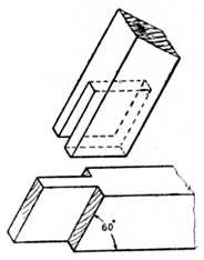
Fig. 170.—Open-Slot Mortise at 60 degrees.
| 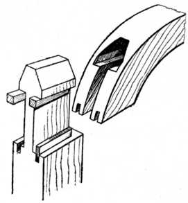
Fig. 171.—Hammer-Head Tenon Joint.
|
Dreadnought File.—At
Fig. 175 is a sketch of a portion of a dreadnought file. This has superseded the old-fashioned home-made float used to clean out the sides of a mortise.
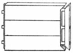
Fig. 172.—Clamping.
| 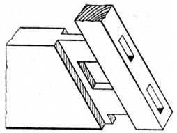
Fig. 173.—Tenoning Narrow Rail.
|
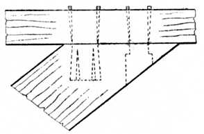
Fig. 174.—Inserted Tenons.
| 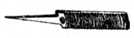
Fig. 175.— Dreadnought File.
|
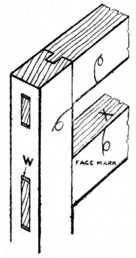
Fig. 176.—External and Internal Joints.
| 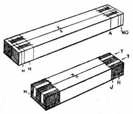
Fig. 177.—Setting out Stiles and Rails for Tenoning.
|
General Rule.—In practically all cases where a single tenon is used the thickness of the tenon should be one-third the thickness of the timber. This leaves the timber at each side of the mortise the same strength as the tenon.
Mortise and tenon joints for inside work may be united with glue. If, however, the work has to stand the weather a better method is to unite the joint with white lead, which is run down to the required consistency with good outside varnish.
Setting Out the Joint.—The principal use of the mortise and tenon joint is in the construction of various types of framing, such as door and window frames. In one or other of its many and varied forms it may be classed as the most important joint in the general woodworking trade. The joint may be used as an internal one, as shown at the lower rail,
Fig. 176, or as an external joint, as the upper rail of the same illustration.
Whatever type of framing has to be made, it is necessary that the face side of the wood be planed up straight and out of winding, and the face mark (as shown in
Fig. 176) pencilled upon it. The best edge of the timber should next be planed up true in length, and square to the face side, and the edge mark (X) clearly placed upon it.
The marking gauge is now set to the desired width, and gauge lines are marked on the wood, after which the waste wood is planed off until the timber is the required width. The thickness is gauged and treated in a similar manner, except in such cases where the finished work is to be of a rough and ready character.
The Two Stiles (or uprights) have their faces turned to touch each other, as shown at
Fig. 177, and their length may be anything from 1 in. to 3 ins. longer than the required finished size. This waste wood at each end of the stiles (see arrow HO) is of importance to the work, as it prevents to a great extent the bursting of the mortise whilst cutting the hole or when knocking together the work. The small projection is called the "horn," and it is cut off after the frame has been put together.
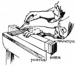 Fig. 178.—Setting Out the Stiles with Marking Knife.
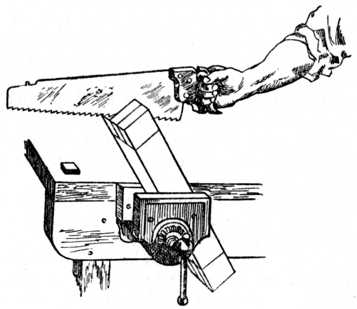 Fig. 179.—How to Saw the Tenons—First Operation.
The two Cross Rails (
Fig. 177), have their faces placed together as shown in the sketch. These rails may with advantage be left
1⁄
2 in. longer than the finished size, and the portion of the tenon (which will protrude through the stile
1⁄
4 in. at each end) may be cut off after the work is put together. (See
Fig. 92.)
Set out the stiles with a marking knife or penknife and a try square, as shown at
Fig. 178. In this sketch only one stile is shown for clearness of representation, but two or more stiles (as at
Fig. 177) may be marked out at the same time, provided a 12-in. try square be used; in fact, marking out the stiles in pairs is to be recommended, as all cross lines will be exact owing to their being marked at the same operation. The cut made by the marking knife should be lightly carried all round the work as the mortising is cut from each edge of the stile, the cutting of the mortising being finished in the centre. The lettering on
Fig. 177 is as follows:—HO, horn; M, position of mortise; H, position of haunching; A, inside line, or sight size, as it is occasionally called.
Set out the cross rails as at
Fig. 177, lower sketch. The lettering in this figure is as follows:—T, tenons; the small piece of the tenon lettered J is called the haunch, and the shaded portion H is cut away to allow the haunch J to fit the haunching of the stile.
The Tenons (as already stated) are generally one-third the thickness of the timber, thus leaving the same amount of substance at each side of the tenon as the tenon itself is composed of. The mortise gauge is set to the required distance and used as in the case of the marking gauge (
Fig. 82).
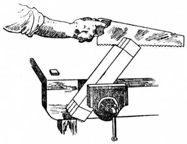 Fig. 180.—Second Operation in Sawing Tenons.
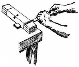 Fig. 181.—Cutting Channel at Shoulder of Tenon before Sawing.
To saw the tenons, place the rail in the vice as at
Fig. 179 and, with a panel, tenon, or hand saw, according to the size of the work, cut down the outside of the tenon line as shown. Reverse your position and cut as shown at
Fig. 180, then place the rail in a vertical position, and you will find little or no difficulty in sawing down square with the shoulder line. Repeat the above methods of sawing until all the tenons are sawn.
Next saw out the pieces at the side of the tenon by the following procedure. Place the rail against the bench stop, or in the vice, and cut a small channel in which to run your tenon saw as shown at
Fig. 181. If you have scored the line deeply with your knife when you were marking out the work, you will have little difficulty in removing a small portion with the chisel. The amount removed in the illustration is, of course, exaggerated. In the small channel thus made place the tenon saw and, guiding the saw blade with the finger so as to keep it upright or square (
Fig. 182), saw away the waste material. Remove the waste material at the sides of the tenons in a similar way, and then saw out the portion marked H,
Fig. 177, lower sketch.
The Mortising of the stiles may next be taken in hand by putting the stiles edgeways in the vice and boring away the bulk of the waste wood from the mortise with a suitable-sized twist bit and brace. This method will save a great amount of noise, as to a great extent it does away with the use of the mallet. Take the mallet and chisel and chop down about
3⁄
8in. as shown at
Fig. 183; then turn the chisel to the position shown at
Fig. 184 and remove the small piece as shown. Continue these two operations until you are about half-way through the wood and then start in a similar manner at the line
a,
Fig. 183, after which turn the other edge of the timber uppermost and repeat the methods shown.
 Fig. 182.—Sawing away Waste Material.
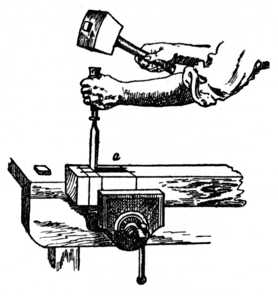 Fig. 183.—Using the Chisel and Mallet for Mortising.
Fig. 185 shows the sketch of a mortise which has its side removed so as to show the method of successive cuts with a chisel when removing the core from a mortise; this, in conjunction with the other sketches, clearly shows the methods of working. In many woodwork examinations the examiners insist that the mortise shall be removed by successive cuts with the chisel, but we certainly advise the removal of much of the waste wood with a boring bit, provided the worker can keep straight and well within the limitations of his gauge lines.
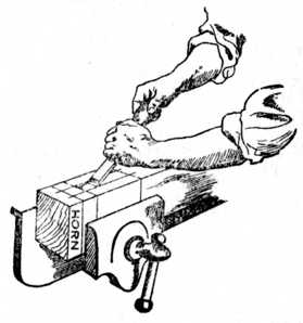 Fig. 184.—Removing Waste of Mortise with Chisel.
Removing Haunching.—After removing the mortise hole, the small portion which is called the haunching will require to be removed with a chisel. This calls for no special remark, as it is clearly shown in
Figs. 187 and 188.
Fig. 186 shows an everyday type of mortise and tenon joint separated; it is used in cases where a straight joint is required on the upper or lower edge of the work, whereas the upper rail of
Fig. 176 shows the full haunch on the top edge. In cases such as
Figs 187 and 188, where the edges of the frames are grooved to receive panels, etc., the width of the tenon is reduced by the width of the groove.
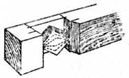
Fig. 185.—Mortise with Side Removed.
| 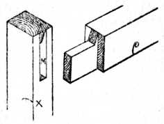
Fig. 186.—The Joint Separated.
|
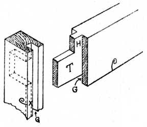
Fig. 187.—Removal of Haunching.
| 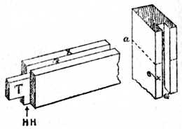
Fig. 188.—Haunching with Groove above.
|
This must be remembered by the worker when marking out his stiles with the marking knife.
Fig. 187 (right-hand sketch) shows the haunch, tenon, and groove G at the bottom.
Fig. 188 (left-hand illustration) shows G (groove) at top, and HH (the haunch) at the bottom. Tenons may be glued together and wedged as shown at
Fig. 176 if for inside work; but if for outside work they are generally smeared with thick paint and wedged up. For light-class cabinet work it is usual to cut the mortise about seven-eighths of the distance through the stile and make the tenon to match it; the edge of the finished work does not then show any indication of the joint, and it leaves a nice clean surface at the edge of the work for polishing or varnishing.
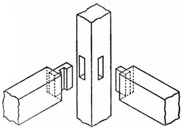 Fig. 189.—Interlocking Joint for Seat Rails of Chair to Leg.
Interlocking Chair Joint.—A joint designed with a view to strengthening the construction of chairs at the point where they are weakest is shown in
Fig. 189. The joint is an interlocking one so arranged that, once the chair is glued up, no motion of the side rail can be possible. The groove in the side rail tenon is cut in such a manner that, on the insertion of the back rail tenon, the joint actually draws up and, having done so, is locked in position. The exact location of this groove is obtained in a similar manner to that used in marking out tenons for drawbore pinning,
i.e., the tenon is inserted in its mortise and the position of the back rail mortise transferred to it, after which the lines are set back by
1⁄
64 in. (approximately) to cause the joint to draw.
From the illustration the construction of the joint should be clear. The method is particularly adapted to a section of rectangular form where one side is longer than the other, such as the back leg of a chair, as this shape allows for the accommodation of the extra length of tenon required.